Views: 0 Author: Site Editor Publish Time: 2026-07-20 Origin: Site
Complex rotational parts present a constant manufacturing bottleneck across precision engineering floors. You turn the primary features of the part on a standard lathe. Then you physically move it to a vertical or horizontal mill. Every single transfer introduces severe alignment errors. You lose your datum points. This fragmented workflow builds up excessive work-in-progress (WIP) and severely extends your overall cycle times. Floor space becomes cluttered with bins of partially finished components. How do you solve this fundamental inefficiency?
You consolidate operations into a single envelope. A turning-milling center provides a robust, single-setup solution. You can effectively finish high-tolerance shafts, geometrically complex discs, and precise internal or external keyways on one machine. This eliminates multiple fixture setups and drastically reduces human handling errors.
This article provides a comprehensive technical and commercial framework. We explore critical engineering constraints and daily setup realities. You will learn exactly how to specify the right machine capabilities without falling for exaggerated vendor claims. Read on to master the transition to integrated machining and significantly boost your shop floor throughput.
Consolidating operations on a turning-milling center eliminates tolerance stacking inherent in multi-machine setups.
Effective shaft machining and keyway milling require specific machine configurations, such as high-rigidity Y-axes, programmable tailstocks, and steady rests.
Transitioning to a multi-task CNC machine requires assessing CAM software compatibility, operator skill gaps, and live-tooling torque limitations.
ROI is driven by cycle-time reduction and labor efficiency, but upfront capital expenditure and tooling costs require strict utilization thresholds to justify.
Every time you unchuck a part, you lose your structural reference. Moving workpieces from a standalone lathe to a separate milling machine creates unavoidable tolerance stacking. You lose critical concentricity between turned diameters and milled features. You also compromise the true position of drilled hole patterns. A multi-task CNC machine solves this problem directly by keeping the part locked in its original coordinate system.
Traditional routing demands a tedious, multi-step process. You must turn the part, queue it for days, move it to the mill, and eventually deburr it manually. This builds a massive production backlog. In contrast, the "Done-in-One" approach eliminates this queue entirely. You load raw bar stock or a blank forging. You unload a completely finished, deburred component ready for immediate quality inspection.
Let us look at the cost versus throughput reality check. You must acknowledge the significantly higher hourly burden rate of these advanced machines. A highly capable mill-turn platform costs more to power, maintain, and tool. However, the total production cost per part drops rapidly. This happens only if you manage your setup times efficiently. You must also eliminate long queue times between operations. Active shop floor management ensures your throughput gains easily offset the higher capital expense. You generate revenue faster because parts ship out the door sooner.
Turning long, slender shafts introduces complex physics problems. Deflection and chatter routinely destroy surface finish and dimensional accuracy. You push the tool against the material, and the material simply bends away. You need specialized, highly rigid machine features for reliable shaft machining. High-quality production demands fully programmable steady rests. These provide intermediate support along the shaft length. You also need heavy-duty tailstocks and flawless sub-spindle synchronization. These systems hold the workpiece securely under heavy cutting loads.
Keyway milling dynamics present another critical engineering challenge. Many shops debate the merits of Y-axis versus C-axis milling capabilities. A dedicated Y-axis is absolutely mandatory for cutting flat-bottom keyways. True linear motion along the Y-axis prevents wall taper. C-axis interpolation simply cannot deliver high-tolerance keyway milling. When the C-axis rotates to simulate linear motion, the cutter geometry leaves a slightly drafted edge. This ruins the precise fit for tight tolerance Woodruff keys or parallel square keys.
You must also carefully consider internal versus external keyway production. Standard live-tooling end mills handle external slots beautifully. They cut aggressively and maintain excellent chip evacuation. However, internal keyways deep inside a bore require broaching or slotting cycles. You can execute these blind internal features within the same machine envelope. You just need proper macro programming and highly rigid static toolholders to withstand the heavy pushing forces.
Failing to calculate the proper Length-to-Diameter (L/D) ratio before skipping steady rest integration.
Using dull end-mills during Y-axis slotting, which pushes the tool off-center.
Ignoring chip evacuation issues during internal broaching cycles, leading to catastrophic tool breakage.
Gripping thin-walled or large-diameter discs is notoriously difficult. High chuck jaw pressure induces severe radial distortion. You machine the part perfectly flat and round in the machine. Then it springs out of tolerance the exact moment it is released. Proper workholding strategies are absolutely vital here. Advanced disc machining often requires full-wrap pie jaws or specialized diaphragm chucks. These components distribute clamping force evenly across the entire circumference of the part.
Face milling and drilling operations also define disc complexity. You can easily utilize live tooling for executing off-center bolt hole circles. Complex face features like face grooving or asymmetric pockets become simple to execute. You rotate the C-axis to position the disc, then plunge the live tool on the Z and X axes.
Sub-spindle handoffs completely change the manufacturing game. Synchronized part-transfer lets you grab the disc mid-cycle while both spindles spin at the exact same RPM. The machine then parts off the material. You can then machine the back-face of the disc automatically on the sub-spindle. This sequence achieves total part completion in a single, uninterrupted cycle.
Use automated air-blast or high-pressure coolant to clear all chips before the sub-spindle jaws clamp the part.
Program a slight dwell time during the synchronization phase to ensure RPMs match perfectly before physical contact.
Utilize soft jaws bored precisely to the turned diameter to prevent marring the newly finished surface.
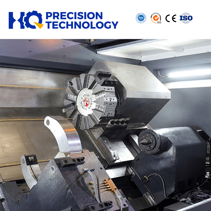
How do you choose the correct platform? The most impactful architectural decision is choosing between a standard turret and a dedicated B-axis milling head.
A traditional turret features individual live tooling stations. It executes much faster tool changes. It excels at standard, heavy-duty turning operations. However, physical constraints strictly limit the live-tool torque and the available clearance. A B-axis spindle changes everything. It is essential for true 5-axis simultaneous contouring. It handles heavy milling tasks effortlessly because it utilizes a dedicated milling motor. You must note it requires a significantly larger floor footprint and a much higher capital budget.
Capability Metric | Turret (Live Tooling) | B-Axis Milling Head |
|---|---|---|
Tool Change Speed | Very fast (rapid index only) | Slower (requires ATC arm transfer) |
Heavy Milling Power | Limited by internal gear train | Excellent (direct drive spindle) |
Turning Rigidity | Maximum structural rigidity | Good, but relies on hydraulic spindle lock |
Tool Capacity | Limited (typically 12-24 stations) | High (magazine holds 40-120+ tools) |
Next, thoroughly verify torque and rigidity metrics. Does the milling spindle actually possess the required torque curve? Cutting tough aerospace materials like 4140 steel or high-nickel Inconel demands serious power at low RPMs. You must review the detailed torque chart, not just the peak horsepower numbers printed on the brochure.
Finally, evaluate the control system and CAM software compatibility. Post-processor availability will make or break your successful setup. Assess whether your current programming software handles synchronized multi-channel operations. If you lack a proven post-processor, your team will spend hours manually editing G-code. Poor CAM integration causes machine crashes and destroys productivity.
Buying a high-end turn mill center introduces distinct, often overlooked setup realities. The programming skill set transition is very steep. Moving from standard 2-axis turning or basic 3-axis milling to multi-channel mill-turn programming challenges even veteran machinists. You manage complex wait codes, synchronization marks, and invisible collision zones. You must invest heavily in virtual simulation software and rigorous operator training.
Tooling ecology presents significant hidden costs. Driven toolholders are highly expensive components. You must choose carefully between BMT (Base Mounted Turret) and VDI (Verein Deutscher Ingenieure) interfaces. BMT offers far superior rigidity for heavy milling cuts. VDI allows slightly faster physical setups but lacks ultimate stiffness. Furthermore, offline tool presetting is no longer just an option. It is an absolute necessity. Setting tool offsets directly in the machine wastes valuable spindle uptime.
Preventative maintenance scales up dramatically in complexity. You must strictly monitor turret geometry. You have to check milling spindle sweep regularly. These machines feature incredibly intricate alignments. For example, a slight bump on a BMT turret requires realigning the entire coupling system. Standard lathes can sometimes absorb minor crashes, but a multi-tasking machine loses its precise Y-axis tram instantly. Stricter, scheduled maintenance protocols keep them running at peak precision. Ignoring this leads directly to rapid degradation of part quality.
Base your purchase decision firmly on your specific, historical part mix. High-mix, low-volume production greatly benefits from the ultimate flexibility of a B-axis machine. The ability to swap specialized tools from a massive external magazine justifies the high cost. Conversely, high-volume shaft and disc families rarely need full 5-axis capability. A rigid Y-axis turret machine works perfectly and cycle times are considerably faster.
Always request a comprehensive vendor time-study before making any commitments. Demand a physical test-cut using your most problematic shaft or complex keyway part. You must validate cycle time estimates and tolerance claims in real life. Never issue a purchase order based strictly on glossy brochure specifications. Take these crucial next steps to guarantee your integration succeeds and throughput climbs exponentially.
A: A turn-mill center offers robust Y-axis travel distances and much larger tool magazine capacities. It boasts massive structural rigidity intended for heavy milling. A standard CNC lathe with live tooling is primarily designed for turning, supporting only light drilling or basic slotting operations.
A: It depends heavily on the Z-axis bed length and the part's length-to-diameter (L/D) ratio. Successful long-shaft machining requires seamless steady rest integration and a programmable tailstock to prevent harmful deflection during aggressive cutting cycles.
A: While highly capable, turn-mills have distinct limitations. They often lack the sheer milling material removal rate (MRR) of a dedicated horizontal or vertical machining center. Their Y-axis stroke is also physically restricted by the lathe-style slant bed design.
A: Yes. For external keyways and standard internal slots, the efficiency is unmatched. Eliminating the secondary setup saves significantly more time and money than the marginal difference in raw cutting speed compared to a dedicated broach.