Views: 0 Author: Site Editor Publish Time: 2026-08-06 Origin: Site
Manufacturers constantly battle tolerance stacking and scrapped components when working on intricate geometries. Traditional 3-axis or 3+2 positional setups often fall short of modern precision demands. They force operators to perform multiple manual refixturing steps. Each setup change introduces tiny deviations. Over a long production run, these microscopic errors stack up. They ruin expensive materials and inflate your cycle times.
Moving to a true continuous 5-axis platform directly solves this bottleneck. You eliminate redundant setups. You dramatically tighten overall part precision. However, acquiring this capability means completely rethinking your shop floor strategy. It is not merely a plug-and-play equipment upgrade. You must shift your entire production methodology. In this guide, we break down the vital architectural choices available today. We explore implementation realities and essential evaluation criteria. You will learn how to select the exact platform your high-stakes manufacturing floor needs.
Continuous 5-axis machining minimizes setup changes, directly reducing the cumulative errors (tolerance stacking) common in multi-surface machining.
Machine architecture (Trunnion vs. Swivel Head vs. Mill-Turn) must be dictated by part size, weight, and existing shop floor capabilities.
Evaluating a machine requires looking beyond spindle speed to assess volumetric accuracy, thermal compensation, and CAM software integration.
Hidden implementation costs—such as specialized tooling, post-processors, and operator training—must be factored into the initial ROI calculation.
You must understand the hidden penalties of multiple setups to justify a new machine. Every time an operator stops a spindle to unclamp, reposition, and reclamp a workpiece, they introduce risk. You spend more money on custom fixtures. You waste valuable hours on manual handling. Furthermore, you significantly increase the risk of scrapping a part due to misalignment.
These challenges make complex part machining notoriously difficult on older equipment. Many shops try to bridge the gap using 3+2 positional setups. A 3+2 setup locks the rotary axes during the actual cut. It works well for simple angled holes or flat planar cuts. However, it completely fails when you need dynamic contouring. Once you encounter undercuts, sweeping turbine blades, or deep sculpted cavities, continuous simultaneous interpolation becomes mandatory. You need all five axes moving together to keep the tool engaged at the perfect angle.
To declare a new machine investment a success, you need strict criteria. First, aim for "Done-in-One" processing. This means raw stock enters the machine, and a finished part exits without manual intervention. Second, maximize spindle uptime. Third, standardize your output quality across high-mix, low-volume production runs. Achieving these goals transforms a machine shop into a highly predictable, profitable operation.
Selecting a machine begins with the physical layout of its moving axes. The way a machine moves dictates the size, weight, and type of parts it can handle. You cannot force a large, heavy casting onto a machine designed for small aluminum components.
The trunnion or cradle style remains incredibly popular. It is best suited for medium-to-heavy parts requiring exceptional rigidity. The rotary axes are located in the table itself. This allows for large tilt angles and dynamic movement. However, you must watch out for payload limitations. If a part is too heavy, the rotary drives will struggle to maintain accuracy. You also need to carefully check table clearance. When the trunnion tilts to 90 degrees, large parts or fixtures can easily crash into the spindle housing.
Alternatively, the swivel head or articulating head architecture places the rotary motion in the spindle. The workpiece sits flat and stationary on the table. This configuration proves ideal for incredibly heavy or oversized parts. You cannot easily rotate a massive engine block on a trunnion. By keeping the heavy mass stationary, the machine achieves superior stability during heavy roughing operations.
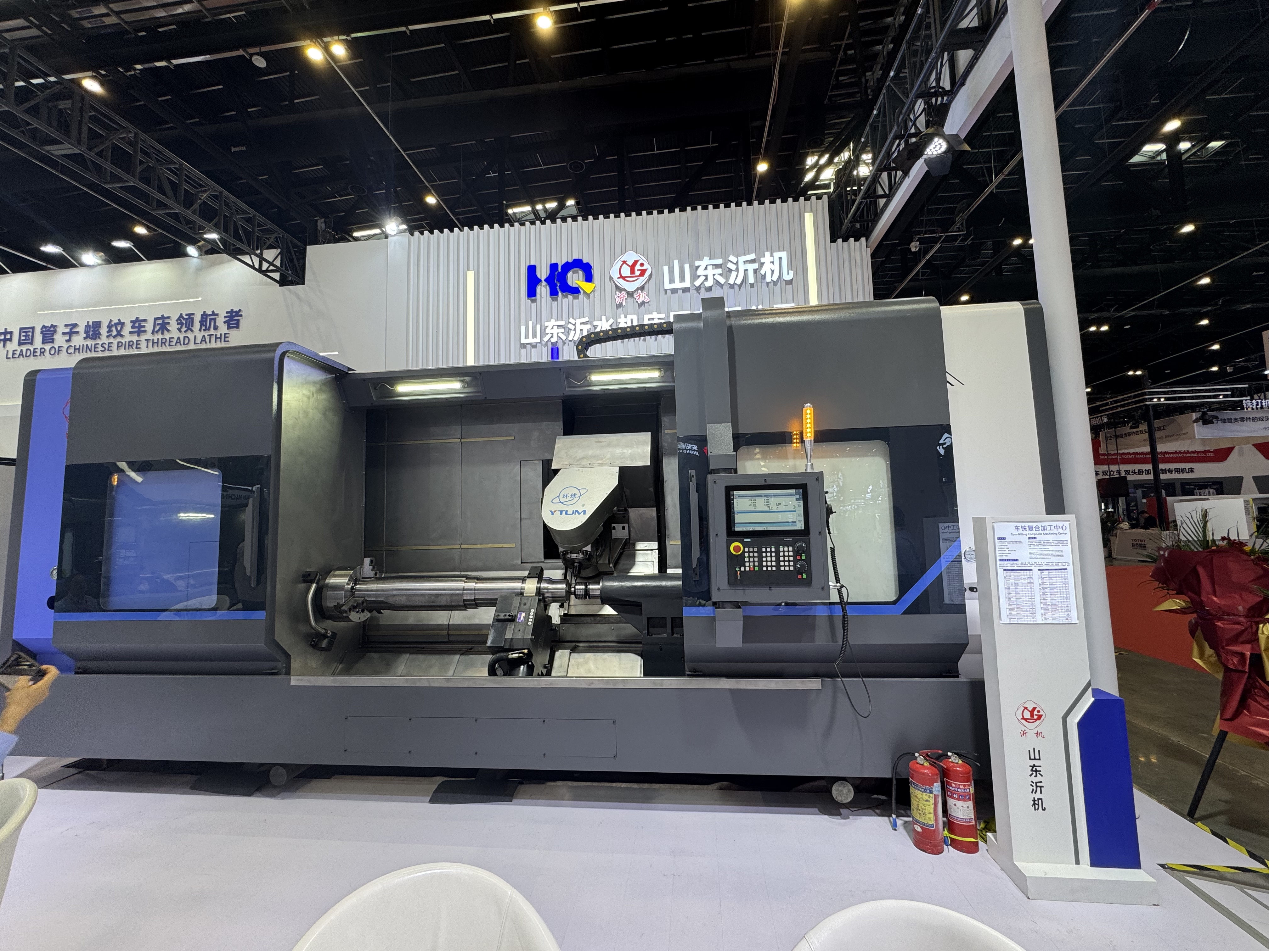
For cylindrical components, mill-turn configurations bridge the gap between turning and milling. Adding a 5 axis CNC lathe to your floor presents the optimal solution when parts require both heavy turning and complex off-center milling. These multi-tasking machines handle bar stock efficiently and execute complex contours without transferring the part to a separate mill.
Use the chart below to shortcut your evaluation process based on part characteristics.
Architecture Type | Ideal Part Profile | Primary Advantage | Limiting Factor |
|---|---|---|---|
Trunnion / Cradle | Small to medium cubic parts, impellers | High dynamic rigidity, rapid simultaneous motion | Table clearance limits maximum part height |
Swivel / Articulating Head | Large aerospace structural components, heavy blocks | Stationary part weight, immense load capacity | Head size limits access into deep, tight cavities |
Mill-Turn | Complex cylindrical parts, shafts with angled features | Done-in-One turning and 5-axis milling | Typically offers shorter Y-axis travel than a dedicated mill |
Different industries push machine tools to different limits. When tackling aerospace parts machining, the primary focus lands on volumetric accuracy and dynamic stiffness. Aerospace components often feature thin-walled monolithic structures. Machining a titanium impeller or a deep aluminum bulkhead requires absolute stability. Any lack of rigidity causes chatter. Chatter destroys the surface finish and fatigues the cutting tool prematurely. You must evaluate how the machine builder compensates for dynamic vibration during high-speed direction changes.
Conversely, precision mold machining demands a completely different capability profile. Mold makers obsess over superior surface finishes. When performing continuous multi-surface machining, the CNC control system takes center stage. It needs advanced high-speed look-ahead algorithms. These algorithms read thousands of lines of G-code in advance. They adjust feed rates instantly to prevent tool dwell marks. Smooth, continuous data processing achieves seamless blending on complex, freeform contours.
You must also address the harsh realities of tooling and clearance. Multi-axis movement places the spindle housing extremely close to the part and workholding. Evaluate the spindle nose design carefully. A bulky spindle restricts access. You often need specialized shrink-fit or hydraulic holders. These slim tool holders allow you to reach deep cavities without causing interference. Short, rigid tools perform better, but they require a spindle head capable of diving deep into the workpiece.
Purchasing the iron is only half the battle. A multi-axis machine is entirely dependent on its software ecosystem. The machine is only as capable as the code driving it. You need a robust CAM package paired with a proven, bug-free post-processor. A faulty post-processor will translate perfectly good CAM paths into disastrous machine movements.
Furthermore, you cannot rely solely on the machine's internal collision checking. You must utilize independent kinematic simulation software. This software creates a digital twin of your machine, fixtures, and tools. It verifies every movement before the program reaches the shop floor. Simulating cuts prevents catastrophic collisions and protects your massive investment.
Thermal stability introduces another major risk. Multi-axis movement generates significant heat in the rotary drives and spindles. This heat causes structural components to expand. Thermal drift destroys precision. To counter this, look for machines equipped with active spindle chillers and chilled ball screws. Linear scale feedback is also essential. Glass scales monitor the exact position of the axes, bypassing errors caused by thermal expansion in the ball screws. Additionally, automated kinematic calibration cycles allow operators to probe a datum sphere and realign the rotary center points in minutes.
Operator ramp-up presents the final hurdle. Acknowledge the steep learning curve right away. Transitioning your team from a 3-axis mindset to full multi-axis thinking takes time.
Send programmers to dedicated CAM training: They must learn spatial thinking and continuous tool vector control.
Master the digital twin: Operators should run complex programs in the simulation software before touching the physical control panel.
Standardize workholding: Adopt zero-point clamping systems early. This eliminates manual dialing-in and reduces setup anxiety for new operators.
Run dry passes: Train operators to slow down rapid traverse rates and execute dry runs on the first few complex setups.
Not all machine builders construct their platforms to the same standards. When comparing options, scrutinize rigidity and construction first. Assess the base materials. Cast iron provides excellent vibration damping. Polymer concrete or mineral cast bases offer even superior thermal stability and damping. Next, examine the guideways. Roller linear guides provide high speed and agility, which suits aluminum aerospace parts. Box ways offer immense stiffness for chewing through Inconel or titanium, though they move slightly slower.
The control system's processing power dictates contouring performance. When processing continuous five-axis data, the control reads thousands of micro-movements per second. Evaluate controls from Heidenhain, Siemens, or FANUC specifically tailored for this heavy data load. A weak processor will starve the machine of data, causing it to stutter and leave gouges on the part.
Finally, vet the vendor on Service Level Agreements (SLAs). Machine downtime burns through revenue rapidly. Dig into their local support infrastructure. Ask if they handle spindle rebuilds locally or if they ship them overseas. Ensure they have spare parts readily available in your region. You also want strong application engineering support to help you tweak complex post-processors during the first year of operation.
Common Vet Mistake: Relying on maximum spindle speed alone rather than evaluating torque curves at specific cutting RPMs.
Common Vet Mistake: Ignoring the physical size of the machine's footprint and how automation (like pallet pools) might fit later.
Common Vet Mistake: Failing to test a benchmark part during the evaluation phase.
Choosing the right 5-axis machining center demands a careful balance. You must weigh geometric capabilities against actual shop floor realities. The most rigid machine on the market will fail if your software ecosystem is weak. A brilliant control system means little if the spindle housing is too bulky to reach deep cavities.
You need to assess part size, primary materials, and required surface finishes. Use these factors to determine whether a trunnion, a swivel head, or a mill-turn platform fits best. Next, fortify your production environment with robust CAM software, kinematic simulation, and thorough operator training.
As a next step, do not rely on generalized brochure specifications. Ask your shortlisted vendors to perform time-studies. Request a live test-cut (run-off) on one of your most difficult, complex benchmark parts. This real-world test exposes the truth behind thermal stability, volumetric accuracy, and software integration before you sign the purchase order.
A: A 3+2 setup locks the rotary axes securely in place during cutting. It positions the tool at an angle, then uses standard 3-axis motion. Continuous 5-axis moves all five axes simultaneously. This synchronized motion is required for machining complex, freeform contours and deep undercuts seamlessly.
A: Yes, it can replace a dedicated mill for parts that feature a high percentage of turning operations alongside complex milling. However, mill-turn machines typically offer much less Y-axis travel than a dedicated milling center. They are best suited for cylindrical or shaft-like components.
A: The most significant hidden costs include high-end CAM software modules, custom-built post-processors, specialized zero-point workholding systems, and independent collision verification software. You also need to budget for specialized, slim-profile tool holders to access tight geometries.
A: Continuous multi-axis movement generally extends tool life compared to traditional 3-axis workarounds. By maintaining the optimal tool engagement angle constantly, the machine prevents excessive rubbing. It also allows you to use shorter, more rigid cutting tools, which drastically reduces chatter and premature tool wear.