Views: 0 Author: Site Editor Publish Time: 2026-11-17 Origin: Site
Procuring capital CNC equipment requires aligning machine architecture with your specific production realities. Choosing the wrong lathe orientation creates daily friction. You will experience cycle time bottlenecks. You might face excessive workholding challenges. Often, compromised part accuracy follows closely behind. You must select the right physical setup for your parts.
Both machine configurations utilize single-point cutting tools. They effectively remove material from rotating workpieces. However, their structural physics solve entirely different manufacturing problems. You cannot simply swap one for the other without consequences. Gravity affects these setups differently. Spindle loads vary dramatically between the two orientations.
This guide breaks down the operational, spatial, and integration implications of horizontal and vertical turning. We aim to support an informed procurement decision. You will learn how part geometry dictates orientation. You will understand why clamping physics matter. Finally, we explore how facility footprints impact layout decisions. Armed with these insights, you can match your shop's machining capabilities directly to your production demands.
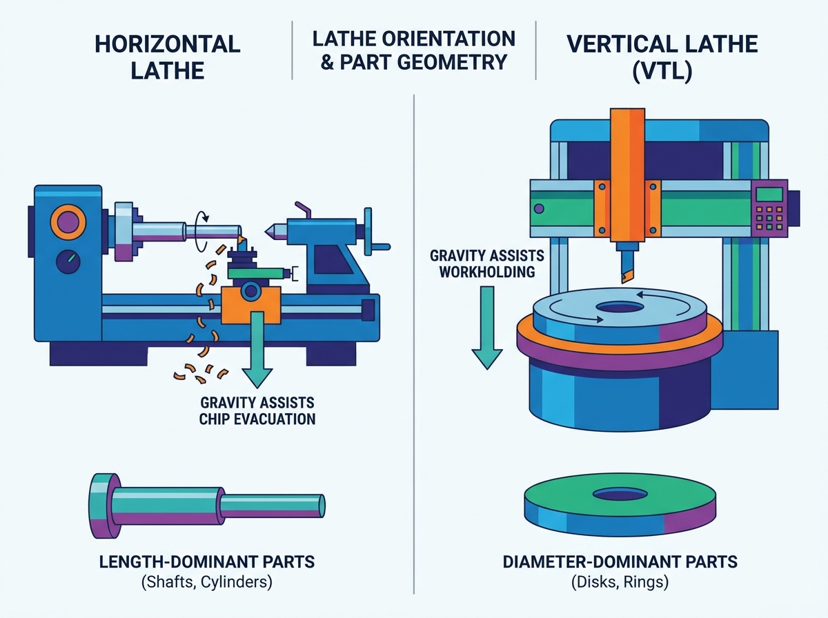
**Part Proportion Dictates Orientation:** A horizontal lathe is optimized for length-dominant parts (shafts, cylinders), while a vertical lathe (VTL) is engineered for diameter-dominant, heavy parts (disks, rings, aerospace casings).
**The Physics of Clamping:** Vertical configurations leverage gravity to seat heavy parts into the chuck, drastically reducing spindle load and clamping distortion.
**Chip Management Realities:** Horizontal configurations naturally shed chips away from the workpiece via gravity; vertical configurations require aggressive coolant strategies to prevent chip pooling inside concave parts.
**Facility Footprint:** Vertical lathes significantly reduce the required floor space relative to the maximum swing diameter they can accommodate.
The standard turning center features a parallel-to-floor spindle setup. The spindle mounts horizontally. The cutting tool approaches the rotating workpiece from the side. This structure defines traditional machining operations. It serves as the default choice for most standard cylindrical components.
A Horizontal Lathe excels in high-throughput production environments. They handle bar stock flawlessly. They produce shafts rapidly. Standard cylindrical components fly off these machines. When you need continuous unattended production, this architecture shines. It provides the most straightforward path from raw material to finished good.
Operators rely on this configuration for several distinct operational benefits. These advantages stem directly from the machine's physical orientation.
Superior Natural Chip Evacuation: Gravity works in your favor here. As the tool cuts material, chips naturally fall downward. Gravity pulls them directly into the chip conveyor below. They do not pile up on the part.
Deep Standard Ecosystem: The industry builds countless accessories for this setup. You have immediate access to standard chucks. Collet systems are ubiquitous. Tailstocks and steady rests integrate easily. You never struggle to find compatible workholding.
Automation Integration: You can easily connect standard bar feeders. The machine accepts raw bar stock through the spindle. This allows continuous unattended production. A single operator can manage multiple machines efficiently.
You must recognize the physical limitations of horizontal turning. The machine requires significant linear floor space. A standard machine paired with a bar feeder occupies a massive footprint. Your shop layout must accommodate this length.
Machining massive, heavy-diameter parts introduces mechanical risks. A heavy part hanging off a horizontal spindle causes "droop." The unsupported weight pulls down on the spindle bearings. This radial load creates premature wear. To counteract this, operators often apply dangerous clamping forces. They crank up the chuck pressure. This excessive force distorts thin-walled parts. You end up scrapping expensive material.
Best Practice: Always use a programmable tailstock when turning shafts. If the length exceeds three times the diameter, center support becomes mandatory.
Vertical Turning Lathes (VTLs) flip the script on traditional machining. The spindle mounts vertically. It faces upward toward the ceiling. The chuck sits flat, much like a potter's wheel or turntable. The cutting tool approaches from above the part. This structural redesign solves specific heavy-industry problems.
You need a VTL for massive components. Precision turning of heavy, awkward-to-clamp parts demands this setup. It handles components where the diameter greatly exceeds the length. Aerospace rings, locomotive wheels, and pipeline valve bodies belong here. The vertical orientation transforms extreme weight from a liability into an asset.
The vertical orientation offers distinct mechanical benefits. Gravity becomes a workholding assistant rather than an obstacle.
Gravity Assists Workholding: Part weight rests squarely on the spindle face. The mass pushes downward. You minimize stress on the chuck jaws. You prevent part deformation. This proves crucial for turning thin-walled rings safely.
Ergonomic Loading: Loading heavy blanks horizontally is dangerous. VTLs offer superior ergonomics. You use an overhead crane to lower heavy castings straight down. The part drops directly into the chuck jaws safely.
High Swing-to-Footprint Ratio: These machines turn massive diameters in surprisingly compact spaces. The machine grows upward, not outward. You save valuable shop floor real estate.
You face unique chip management challenges here. Deep internal cavities can easily trap chips. Since gravity does not pull them away, they pool inside the part. You must implement high-pressure coolant strategies to flush them out. Failing to do so causes recutting. Recutting destroys tool inserts rapidly.
Tool-change clearances also require careful calculation. Large-swing parts consume most of the machining envelope. When the turret indexes, long boring bars can easily crash into the workpiece. Programmers must establish safe retract zones.
Feature | Horizontal Setup | Vertical Setup |
|---|---|---|
Spindle Orientation | Parallel to floor | Perpendicular to floor |
Ideal Part Shape | Long cylinders, shafts | Wide disks, rings, flanges |
Loading Method | Manual, Bar Feeder, Gantry | Overhead Crane, Robot Arm |
Chip Evacuation | Excellent (natural fall) | Poor (requires flushing) |
Selecting the right machine requires methodical analysis. You must evaluate your specific production parameters. Guesswork leads to inefficient machining. Consider these three dimensions carefully.
You must analyze the Length-to-Diameter (L:D) ratio of your parts. This metric reliably dictates your machine choice.
A Horizontal Lathe performs ideally for L:D ratios greater than 1:1. Long shafts require this setup. You can easily support the tail end. Conversely, vertical setups handle L:D ratios less than 1:1. They excel when part weight exceeds the safe lateral load limits of standard spindles. If the part looks like a pancake, go vertical. If it looks like a hot dog, go horizontal.
Your material handling strategy dictates machine architecture. Continuous production demands specific loading systems. You must match the machine to the automation style.
Horizontal machines pair perfectly with bar feeders. Raw stock pushes through the spindle continuously. Gantry loaders also integrate smoothly for high-volume, low-mix turning. The side-access doors make gantry integration straightforward.
Vertical machines reject bar feeders entirely. They are physically incompatible. Instead, they suit robotic arm loading. A robot can pick up heavy slugs and place them down into the chuck. For massive castings, overhead crane access remains mandatory. The shop ceiling must accommodate this lifting equipment.
Machine rigidity directly impacts part tolerance. Spindle deflection ruins surface finishes. It causes dimensional inaccuracies. You must understand how weight affects the bearings.
Extended, heavy parts in horizontal setups risk spindle droop. The radial load pulls down against the bearings. You must use a tailstock to counteract this force. Without support, chatter occurs. Precision suffers immediately.
Vertical setups inherently minimize deflection on heavy parts. The mass acts downward. It aligns axially along the spindle bearings rather than radially. Thrust bearings handle this axial load beautifully. You maintain tight tolerances on massive parts effortlessly. Clamping distortion disappears because gravity holds the part flat against the chuck face.
Beyond the cutting physics, you must evaluate how the machine integrates into your facility. Structural limitations within your building often force a decision. Machine capabilities continue to evolve. You must assess current technological offerings.
Evaluate your requirement for standard turret configurations versus live tooling. Industry demands single-setup machining. Horizontal machines currently dominate the "done-in-one" multitask market. They frequently incorporate sub-spindles. They feature robust Y-axis capabilities. You can turn, mill, drill, and part off a component in one cycle. The part drops out completely finished.
Vertical Turning Centers (VTCs) are steadily catching up. Builders now integrate live tooling into vertical turrets. However, the ecosystem remains less standardized. Sub-spindle operations on vertical machines exist but remain highly specialized. If your parts require complex multi-axis milling after turning, horizontal platforms generally offer a wider array of proven solutions.
Your building architecture directly influences machine selection. You cannot ignore square footage constraints. Ceiling heights matter.
Vertical lathes require significant high ceiling clearances. You need room for overhead crane loading. Furthermore, the vertical Z-axis stroke extends upward. The machine tower can reach impressive heights. Measure your roof trusses before ordering.
Horizontal lathes demand extended linear square footage. The machine itself takes up floor space. Adding a 12-foot bar feeder doubles that footprint. You need clear aisles behind the machine for bar loading. If floor space is tight, a horizontal setup might force you to rearrange your entire cell layout.
Decision paralysis often strikes during procurement. Use these targeted checklists to finalize your choice. Match your dominant production scenarios to the corresponding machine type.
Your primary raw material arrives as bar stock.
Your typical parts are longer than their diameter (high L:D ratio).
You require standard continuous bar-feed automation.
Chip evacuation on deep-hole boring operations is a strict quality requirement.
Your facility lacks heavy overhead crane infrastructure.
You need extensive sub-spindle transfer capabilities for secondary operations.
You predominantly machine heavy castings and large forgings.
Your product mix includes large O.D. wheels, flanges, and aerospace rings.
Operators struggle to safely load and clamp heavy parts horizontally.
Floor space is at a premium, but your ceiling height is ample.
Clamping distortion currently causes out-of-round scrap on thin-walled parts.
You utilize robotic arms to load heavy individual slugs.
The choice between horizontal and vertical turning is rarely a matter of preference. It is strictly dictated by part geometry, mass, and factory layout. You cannot force a heavy, awkward casting into a horizontal chuck without risking safety and quality. Likewise, you cannot efficiently run continuous bar stock through a vertical spindle.
To move forward, conduct a time study on your heaviest, most problematic part. Request a run-off from machine tool builders. Ask them to demonstrate cycle times for both configurations. Make sure you factor in the load and unload times. Cutting time only tells half the story. Crane loading a heavy part into a vertical chuck often saves minutes per cycle compared to dangerous horizontal loading. By matching your physical machine architecture to your specific part geometry, you ensure a smoother, safer, and more productive shop floor.
A: Yes. While they cannot use traditional bar feeders, vertical machines are highly compatible with automated systems. You can successfully integrate robotic arm loaders, automated pallet pools, and carousel systems. These mechanisms excel at picking up individual heavy slugs or castings and placing them directly down into the vertical chuck.
A: Tool life heavily depends on rigidity and chip evacuation. A horizontal setup generally offers better tool life during deep internal boring because chips fall away naturally. Conversely, a vertical setup offers superior rigidity for heavy, interrupted cuts on large castings. This rigidity minimizes vibration, potentially saving insert edges from premature chipping.
A: Machine limits vary by builder. However, shops typically transition to vertical setups when individual part weight exceeds 150 to 200 lbs. Beyond this weight, lateral manual loading becomes dangerous for operators. Furthermore, hanging heavy mass horizontally risks accelerated spindle bearing wear due to excessive radial load.
A: Horizontal machines generally perform better for deep-hole boring operations. Because the tool operates parallel to the ground, gravity pulls the chips downward and out of the bore. In a vertical machine, the chips tend to pool at the bottom of the deep hole, requiring high-pressure coolant to flush them out effectively.